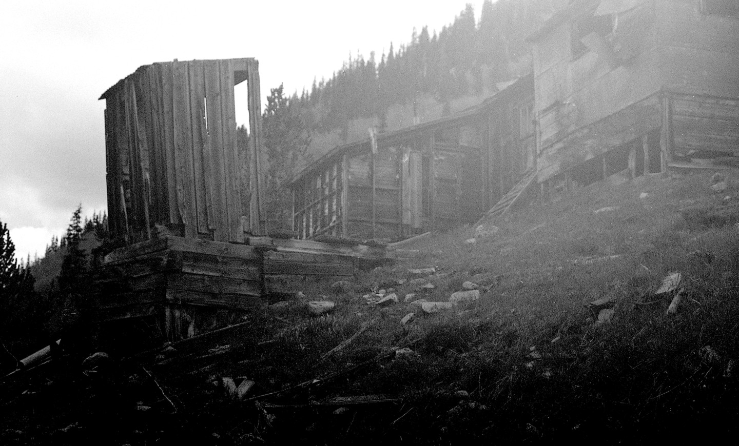
Followers

07 September 2024

7th Street Shops- Ma and Pa Balance Post 29

A custom weight helps tailor this model to its intended purpose

With the weight finalized in the Gem Models 4-6-0 the locomotive pulled a train of 17.75oz with "rare" slipping. Additional weight was loaded progressively onto the 1oz test car until the slipping increased to substantially more spinning than forward motion. The maximum weight with any forward motion was 23oz therefore I rated the engine

Each disk is about 0.35oz or 0.7oz in the cab

tonnage as 17,75oz on a 2% grade.

Up to this point, I had used the test car (with Intermountain Models plastic trucks) with a range of weights that could be combined to any multiple of 1/4oz. It was time to take the investigation to the next level.

I still have an old copy of  HO Primer by Linn Wescott. This was the go-to hand book for HO modelers in the '60s and '70. 

I briefly review the chapter on rolling stock and found that the recommendation was 1/2oz for every inch of car plus 1 extra ounce. A 40' boxcar in HO is 5.5" long over the end sills. According to HO Primer and the NMRA such a car should weigh 3oz with one additional ounce overall for a total of 4oz.

The weighted test car was 18oz with no slipping @ 2%

Of course in those days Truck technology wasn't quite what it is today. On the other hand, mass produced model locomotives shells were all metal and rather more heavy. They could pull more.

I collected together a train's worth of Moore & Moore Lines freight cars - in this case 5 Central Valley Old Timers. I checked and marked the weight of each cars in order to tally the total train "tonnage". The M&ML cars are 36 footers or just under 5" long. They should weigh 3.5oz. according to the given sources but they are all between 2.2oz and 2.95 oz - a little light. The

total weight of the 5 cars is 13.25oz. The flat car with an incomplete caboose on top weighs 3oz. The total train weight is 16.25oz.

The Gem Models Ten Wheeler marched up 2% with 20 1/4oz not counting the 3.25oz tender

Initially, the locomotive did well since the train weight was well below the engine's proven capability. Then I did something radical; or so it might seem these days (we being conditioned to high quality plastic trucks that will take off if you just look down hill). I oiled all of the axles including those of the tender. The cars I used for testing are true Central Valley kits that came with their wonderful metal trucks.They have been upgrade, however, with NWSL fine scale (Code 88)  axle sets. The results were quite interesting.

Again, weight was progressively added to the flat until at 22oz the wheel slip was notable (meaning; the drivers clearly slip with every revolution). I backed the weight off and redefined the engine's tonnage as 20oz at 2%. This was an increase of more than 2oz and that can make it possible to add 1 more car to the train.

The average Central Valley house car on the M&ML weights 2.65oz. This locomotive can handle a 6 car train plus caboose over the steepest hill on the line. Of course, that is longer than the line's only passing track.

Worn 40lb rail from Schwanders CO - C&Sng

Slipping wheels are not a to be tolerated. Slipping wheels can mean tread wear or in the case of stainless steel tires, rail wear. (Both are prototypical by the way; but nobody really wants to model that!) .

To summarize, handling locomotive weight intelligently can increase your enjoyment of the hobby. The encumbrances are that there are many variables, yet seemingly, there is very little discussion about the topic. Of course diesel (pronounced "disease-zel") modelers need not be as attentive because weight is pretty linear in their world. Intelligently balanced, a model steam engine may well out-pull a like model mindlessly crammed full of lead - even if the latter weighs more. Adding too much weight can also mean a shortened life of the power train. 

Below are the stats on this model and a brief of the steps taken to arrive at the best pulling capability.

Tests model; Gem Models 4-6-0. Built by Olympic Models (Tokyo) 12-6-'62.

Modernized Power Train; Sept '18 with NWSL 1630D-9 motor (0.75oz) with flywheel (0.25oz). Balance w/o boiler weight = +1.0oz to front.

Procedures: (Note all train weight total values exclude weight of tender.)

1) (No boiler weight) Added 1/2oz to cab; @ 2% locomotive pulled 9oz plus 1oz car = 10oz Occasional slipping.

2) Added original boiler weight (1.7oz) plus 1.75oz to cab; Train weight of ~20oz @ 2%. Stalled (full wheel slip).

3) Added 5/8"o.d. x 1.1" tube w/ buckshot for total 1.25oz to boiler. Pulled 13oz without weight to cab. Added 0.75oz to cab. Pulled 17.75oz total  @ 2%. Engine weight = 8.25oz, tender = 3.25oz, total locomotive 11.5oz

Then:

@2%, 5 cars plus caboose on flat = 16.25oz.total. Occasional slipping. Checked and lubricated all car and tender axles. Progressively added 5oz for 21.25oz total (until common slipping). Reduced train weight by 0.75oz to 20.5oz for rare slipping - Total train weight 20.5oz. The  Moore & Moore Lines has officially rated this locomotives tonnage @ 20oz on a 2% grade.

Central Valley cars of the Moore & Moore Lines weighed and marked for tonnage purposes


24 August 2024

7th Street Shops- Ma and Pa Balance Post 28


Gem Models HO Maryland & Pennsylvania 28 (4-6-0) constructed 6 Dec. 1962, Tokyo Japan
In the past few posts I have discussed the tools, principles and a bit of the history about the balance of model steam locomotives. Hopefully, the reader has a better understanding of the importance of balance.

Model Railroading offers satisfaction from the simplest amusement of watching the wheels go 'round 'n' 'round to delving into the complexity of game play that we play called, "operation". It all hinges on one definitive feature - animation. At 7th Street Shops miniature locomotives are FIRST machines and then models; because, they must move. All of the rest of it doesn't really matter if they don't move. 

HOW they move is important to how they meet our expectations. Maybe the point isn't clear; if they don't meet our expectations, even mobility becomes frustrating and meaningless; and that will overshadow the enjoyment of our game. Watching the wheels go 'round 'n' 'round is much more enjoyable when a respectable train comes along with them. Pulling is important and balance of an engine is key to that function.

Without boiler weight engine is heavy to front

So. Let's do it.

In the photo (left) the open pole motor was replaced some years ago by a motor similar to the Can motor shown. The original motor weighs 1.5oz and the Can weighs 1oz with a 1/4oz flywheel attached. The engine (that part of a locomotive that generates the power to move) weighs 6.9oz without the boiler weight (seen on the scale). The overall balance of the model is rather heavy to the front as seen by the beam drop. The 2 axle pony truck, still in place, has very little weight to contribute to this. Note how far back the operational center of the driver coupling is on Ten-Wheeler types. Despite the long front end the weight still needs to bear evenly on each of the drivers. This certainly contributes to the type's tendency to be front heavy.

In this case, the three driver axles are spaced evenly apart; that makes it easier to see that the engine is on the beam's rocking axis. The model's relative center of balance is substantially ahead of the coupling's mid point. It took an extra ounce on the cab roof to balance the engine (below right).

Adding 1 oz to the cab roof balances the engine

Without any  added weight in or on the engine the locomotive struggled to pull even5 ounces up the 2 percent grade. 

This is a good place to point out that the engine pulls not just the weight of the train but that of the tender as well. This tender weighs 3.25oz. In action it contributes nothing to the pulling efficiency of the engine and plays no part in balance other than pull-down along with the rest of the train. Generally, there is no advantage to an over weighted tender in terms of electrical pick up; clean the truck tires (don't forget the bolsters pads either) and the track and electricity will flow to even a lightweight tender! However, as a light car at the front of the train it needs to have some weight so that the load does not pull it off of the track. The 3.25oz of this tender is just about right. If you remove weight and find that the tender derails when the locomotive is pulling, add back weight a little at a time until the problem is resolved. Any more is waste and robs the engine of pulling capacity.

Unweighted engine could not pull 15oz up 2%


I added 0.5oz to the cab roof. It took 1oz to balance the engine but I don't want perfect balance. To counter pull-down I left 0.5oz to the front. I still did not add any weight into the boiler. With this simple addition the locomotive pulls 10oz up the grade though with some slipping.

To establish the Tractive Effort of a locomotives I run the model as slow as it will go so that I can detect wheel slip. The "tonnage" is then defined at the greatest load before the wheels start to slip at slowest speed above stalling. Of course, slight undulations in the track may cause an occasional slip. If the model does stall bump up the voltage until it moves again - without slipping.

I finally installed the original boiler weight back into the engine and increased the cab weight to 1.75oz. The train weight was increased incrementally until it was over 22oz and the wheels started to slip more severely. At this point I was confident of a coarse of action that I'd wanted to do for this model.

I don't need a lot out of this or any of the Moore & Moore Lines motive power. The Ten Wheeler will probably never be expected to haul more than two or three smaller wooden passenger cars that only weigh 5 or 6oz each.

5/8" brass tube with turned brass caps

The M&ML cannot handle long trains and its longest (and only) passing track has just 33" of train capacity. The ruling grade on the M&ML is 2%. 

With these considerations I built a custom boiler weight that is greater in diameter yet shorter in length than the original. I was willing to give up a little weight in order to make room for electronics inside the boiler. It is a trademark of 7th Street Shops DCC installs that rarely are there more than 3 break away wires between the tender and the engine. Sometimes there are none.

The original boiler weight wasted a lot of room inside. It is less than 1/2" in diameter yet 1 3/4" long. Even so, it weighs 1.6oz - it is solid brass. The new weight is a 5/8" O.D. brass tube 1.2" long with turned end caps. It weights 1.25oz filled with buckshot. It fits the target location better and leaves plenty of room in the smoke box for a current storage device or even a small speaker plus the components for the headlamp.

The advantages of using buckshot in a tube is a degree of flexibility to fit the desired location and other components and considerations. An added plus is that there are no unsightly chunks of metal visible from track side. The trade-offs seem worth it.

I also added a smaller tube positioned inside the 5/8" tube to accept the saddle screw. The screw is long enough to pin the weight in place. The alignment of this "pocket" is marked on the end of the weight to aid in positioning the weight during assembly.

The mark indicates where the hole for the boiler screw is aligned

I gave up 3/10ths of an ounce in the boiler and a corresponding amount in the cab. The overall weight of the engine is now more than it was after the motor was replaced. But it is 3/4oz less than the greatest amount with the original boiler weight as I described above. So now how will this model perform with its newest configuration?

I'll tell you about it next time.


19 August 2024

7th Street Shops: The Imbalancing Act - Post 27

Something happened in the late 1970s and 1980 that had a direct bearing on the topic of this post. Motor miniaturization advanced because high potency magnets that used rare earth materials became available. This allow significant reduction to all parts of the motors yet increased their efficiency. Model manufacturers realized the advantages of the new technology and began to use them.

The engine and beam are at balance with the small amount of weight added to the cab roof

Before Can motors, heavy open pole motors would have had a significant impact on model balance and of course, the motors of steam models are typically over the back axles. The worst condition of imbalance is for the rear drivers to carry more of the weight. I'm nearly convinced that the entire purpose of adding boiler weight to a brass model was to counter-balance the weight of the motor that was used.

By the time Can motors caught on there were already millions of brass models with open pole motors in the world. Many models already had worn out motors. But of course, brass models do not get throw away. Rather, they usually wind up in a closet tucked safely in their box. Sometimes they were fixed but the arrival of the new motors logically inspired many modelers to fix non-operating models. Then many more old motors were simply replaced because the "modern" types were demonstrably better.

When commercial DCC came along more old motors were replaced because they could easily spike several amps more than the decoders could handle. Conversely, the better Can motors typically operate at less than a few hundred milli-amps.

It's always a good idea to replace that old motor. They are inefficient to begin with but over time magnets tend to loose potency and of course, this only degrades motor performance further.

However, there is a caveat to replacing an original open pole motor with a smaller Can type. 

I have no information that would describe the in-house approach various manufacturers used to address balance of the models they produced but clearly most of them did. The best builders were very good at it. You can determine this for yourself if you have the tools and a model that hasn't already been been altered. But herein lies the problems. Set aside that the number of untouched models is dwindling; how do you actually determine engine balance? What tools - and where do you get them - do you need to do that? You might be able to diminish the issue with a lot of trial and error but without the tools and know how, your success will likely be a matter of luck

The manufacturer probably engineered the balance of a given model based on known data that included the weight of the motor. After the fact, when we replace that old motor we don't particularly have all of the data. But we can weight the two motors and find their differences. We will likely find that the old motor is 2 or 3 ounces heavier. What ever the difference, it will be displaced to the front axle when the new motor is installed. This isn't as serious as overburden of the rear axle since train pull-down will relieve some of that but it still robs the model of performance. 

What compounds the problem is that it isn't detected when the deed is done; unless the installer knows what to expect. There isn't an overt change in how the model runs. Rather, the issue distills into observation of the model over time and it is slowly realization; this model just doesn't pull quite as good as it use to... what happened? Then, as is often the case, the issue is further buried under the arbitrary addition of more weight. Folk, the laws of physics are immutable and they do not forgive.

Motor to left is typically replaced with the  can motor at top.

In the photo to the left the large open pole motor is readily replaced by the can motor (top). Another NWSL 2032D-9 is disassemble at right. That armature measures just 13mm in diameter and the total weighs is less than 1.5oz. The open pole motor weighs 3.6oz and has an armature nearly 18mm in diameter. The Can motor is more powerful but if it replaces the open pole motor more than two ounces would be improperly displaced. A motor's power becomes irrelevant if the drivers do not engage the rail tops.

The condition that is manifest in an unbalanced model is that one or more of the driver sets float. It is true that springs can also cause drivers to float; where they pass above the rails ineffective. What most often causes this condition however, is a model that is out of balance.

Model balance is not well understood by the hobby community. I took a model and the balance to a "new" local hobby shop to show the younger proprietor what the beam could do. It was quickly apparent none of what I shared with him was of any value. Nor was it certain he even understood the point. The "math" of my situation became very clear as I looked around at all the modern diesels in the store. Is the age of steam over in the hobby? Tractive balance of steam engines is of no real relevance to diesel traction and the coming generations of modelers are progressively less connected to that old railroad charm. The response to diesels traction issues (as well as shays and other shaft driven models)  is that blunt-instrument paradigm; add more weight wherever it will fit.

Unfortunately, this topic has always been obscure and digging into old magazines to find related discussions will bear that out. When discussions of poor pullers come up the general and relatively easy solution is "add more weight" - wherever it will fit. Adding weight indiscriminately can exacerbate a balance error. It can also create risk to motors, bearings, driver tires and perhaps other power train parts.

Yet, again, even if the modeler suspects a locomotive is out of balance how does he effectively identify the causes and arrive at the proper solutions? Does he even know what the factors are and where does he get the tools needed to accomplish all of this?

Beam is gauged to (lt. to rt.) O, S, On3 (not shown) HO and Sn3

As I described in the last post the rewards are clearly worth the effort to find practical solutions to this issue. Over the years I have gathered materials and thought about how they should be used. I quickly recognized that a rocking beam would be the best means to gauge balance.

I recently built the beam that you see here since I know of nothing commercially available. This tool is substantial in that it is heavy, rigid and smooth in operation. The beam itself is milled and calibrated and it is grooved for the gauges we service. The only thing that moves the beam (and only in a rocking motion) is any slight imbalance of weight.

Using the beam is relatively simple if all the principles are understood. The.entire primus is based on centering the driver coupling over the proper location of the beam's cross axis. A "driver coupling" is the joining of 2 or more axles by means of linking bars, or more commonly, side rods. What matters most to achieving balance of a model steamer are the two outboard axles (front and rear) and the exact mid point between them. Inboard axles are incidental to these 3 elements. It is the mid point between the two end axles that we must place exactly at the rocking axis of the beam.

Before the actual test is conducted we may remove lead and trailing trucks. They have little effect on the driver coupling itself because most of their weight is born by their own axles. Therefore, unless they are massive multi-axle trucks that would bear down on the beam itself, they probably won't significantly alter the balance on the drivers.

At this point loose pieces of weight are used to bring the engine into balance. In the title photo a few small weights can be seen on the cab roof. Weights should rest somewhere on the model itself. Placing them on the beam within the dimensions of the model is permissible but I prefer to place the weights directly onto the model as near to their mounting locations as I can determine. Certainly, weights should not be placed on the ends of the beam.

Buckshot is added to the cup a little at a time

The two places weight usually winds up are in the smoke box and in the cab roof.  Placing weight evenly over the driver coupling can achieve greater traction without too much impact on balance but that is not always easy to achieve. If the model is already balanced this is the only place that weight can be added "where ever it will fit", but the weight must be distributed evenly within the center-to- center limits of the coupling. Keep an eye on the balance.

I sometimes find a small measuring cup useful when seeking the point of balance. It is easy to add just a few bee-bees at a time since exact balance can be achieved in this way. Be careful however; buckshot and bee-bees are notorious escape artists and a bunch of tiny balls on the floor can be hazardous.

Once balance has been achieved I adjust the weight equation to lean 1/4 to 1/2 ounce to the front of the engine. Again, this goes to what happens when an engine pulls a train. There is a slight pull downward on the rear axle as the train weight takes affect on the engine; therefore tilting the weight slightly forward helps to counter that pull down. At this point I install the weight and test the improvements to the model's "Locomotive Tractive Effort" (LTE). 

If you suspect this is the reason some of your prized brass steamers are disappointing pullers and you don't want to do this yourself contact 7th Street Shops. We can help.

When we continue this discussion I will share a "live" example to demonstrate how adjusting balance improves performance.

If you want to leave comments you will first need to "Follow" this blog.


30 July 2024

7th Street Shops: ? of Balance - Post 26


-

Balance; this HO Pacific (Key Imports A.T.&S.F. 1226) is about to undergo a balancing act
Several years ago a client sent a P-B-L, S scale, narrow gauge K-36; similar to the model shown below. Among other cosmetic repairs he complained that the model did not pull well. His layout included a 2 percent grade helix where the model could only pull 8 freight cars to the top. This was disappointing as the K classes were the largest locomotives on  D.& R.G.W.narrow gauge and to this day they pull longer trains of similar cars up steeper grades on the Durango & Silverton R.R. 
 
The model did not meet his expectations. He had several of the 480 class big mikes and it is assumed they all did better than his 486.
 
The issue of model traction is a subject that I've studied for many years. On my Sn3 C&S layout I discovered that the small moguls and consolidations were unable to pull even a single brass passenger car up hill from Hess to Bath. Swallowing my own disappointment I defiantly decided I would come to a better conclusion than to just set those models on a shelf - as it seemed Overland thought little more of their product than that. I had several intertwining ideas about what to do but after the K-36 I began to realize a more deliberate approach to the problem. Unfortunately, I don't have the layout anymore nor do I have time to work my models. Instead I've set out to enhance our services to the benefit of our clients at 7th Street Shops.
Even this finely crafted P-B-L K-36  is subject to physics
 
Let's examine the issue a little closer. When a model doesn't pull well it seems the common assumption is that it lacks sufficient weight. But my experiences show time and again simply adding weight is more like  trying to pour a gallon of water into a 1 quart jar. When more weight is added to say, a four axle coupling and only 1 axle is actually pulling, adding weight is a waste and the issue is not addressed.
 
Most manufacturers add ample weight to their models. Adding more weight starts to burden the power train (motor, gears and mechanism). Too much weight increases wear on these parts and they may prematurely fail. The reality is that simply adding weight to a poor puller is likely not the correct answer.

The fundamental problem is that of floating drivers whereby one or more axles do not sufficiantly press their wheels onto the rail tops. Two factors cause floating drivers; incorrect springs and a driver coupling that is not properly balance. For this reason it should go without saying that this topic is generally exclusive to side rod steam locomotives. In other words, these issues rarely effects sidewinders, diesels and other models that depend upon powered or shafted trucks rather than reciprocating drivers.

We will discuss springs at another time (springs, not suspension). True driver coupling suspension is rarely found on production models).
 
You have to be pretty dedicated to properly determine the specifics of an imbalanced driver coupling. The determination process is a bit tedious but the real impediment is the availability of the tools required to investigate the state of balance.You cannot fix what you can't determine needs fixing.
 
You likely have noticed a few of my tools in the photos shared here. The beam seen in the title photo didn't come by UPS. It came out of our machine shop. Nor did it just happen. When I started I did not know what features it would need. This beam is the result of a developmental process. When I tested Patrick's K-36 I temporarily fastened a small diameter rod to the table top and attempted to balance a plate/beam over it. This arrangement was difficult to manage because it was very easy to move the plate and or rocker rod when the engine was set upon the plate. But I persisted and until I could determine that the engine was out of balance and which direction it was too heavy.
 
The second tool is a scale with some degree of accuracy. I already had a postal scale. While it can't be relied upon for gun powder accuracy or exact postage due for shipping it does quite well for this purpose.
 
There must also be some type of weighting material that offers both flexibility and the ability to attach it to the model. I have a box full of lead pieces that I use for this purpose. You will need material to be used to make the corrections permanent as well. 
 
I've mentioned our machine shop. The ability to make boiler weights is often a valuable asset. Of course, the average modeler may only have an occasional need to do this but when many models come thru the door - all in needing some type of attention - the need becomes apparent.

The last "tools" are more abstract; that of knowledge. I'm sure there is a cadre of experts out there (there always are) with this knowledge (which is why we see so much published on the matter) but frankly, very little is readily available and at times, what I see suggests that this knowledge is generally far from the average modelers purview. What I've learned is from hard earned experience and a few bits and pieces from old magazine that offered hints along the way.

I'll finish this post by sharing the rest of the story of my client's K-36. This will be enlightening.

I determined the model had come from the factory out of balance; there was no indication of any modifications. The boiler weight was soldered to the shell per usual so actually removing it would be very difficult. Therefore I cut away material where it was excessive and added weight until the model balanced on the makeshift beam. This attained the goal of equal pressure of all 8 drivers on the rails. What ever a steam locomotive can do with what ever weight available to it, equal pressure will maximize its tractive effort to that measure. This is the reason cramming lead into every nook and cranny is not usually necessary.

I returned the model to the client and when we talked on the phone some days later this is what he told me; "I don't know what you did to this model but where it could only pull 8 narrow gauge freight cars (in S scale they are roughly the same actual size as an HO 40' standard gauge car) it can now pull 18 cars up the same 2 percent grade on a curve!"

The K-36 experience has not been unique. With the proper tools and working knowledge the results are consistently that direct. After balancing the Sante Fe engine in the title photo above it is capable of pulling 12, 40' freight cars - 42oz (each weighing 3.5 oz) - up a 2 percent grade. The weight in the model was not increased or decreased from the factory; merely redistributed. The engine, itself  a medium  size, only weighs 13oz. The tender weighs 6 oz and is in addition to the 42oz. The effective pulling is determined at the point just before the drivers begin to slip. With slipping it can pull a few more cars.
 
HO (40' box) and Sn3 (30' box) cars are roughly the same size (6" L x 1.5" W x 2" H @ 3.5oz ea.)
 
We will continue this discussion in a future post.


26 May 2024

Shifting Gears - 7th Street Shops Nuts & Bolts Post 25

Let's shift gears. Let's talk about 7th Street Shops operations. Generally, this blog is never going to be a "How To" center on how to do stuff. I may from time to time share some ideas about what we do but it isn't an objective to comprehensively teach anyone any of it. However, I've always intended to demonstrate results expressly for the purpose of establishing confidence in our services. This is also the place to discover more about our company as the last 2 dozen posts have hopefully demonstrated.

Art Lort's HOn3 K-27 (paint & lettering iirc) 2010

7th Street Shops will be 15 years old this summer. We started the business at the encouragement of a few fellow modelers in the Denver area after the technical field I was in dried up. 

By July 2009 I was pretty much out of money and was rather cornered financially. My good friend, Patrick Tillery, who happened to modeled D&RGW Sn3 (code for P-B-L),  encouraged me to customize and repair model locomotives - particularly his. I had already been doing that sporadically for a few friends around the metro area so he was quite confident in my ability and supplied numerous jobs for years thereafter. Thank you, Patrick! (Some of you may know him as one of the mail order guys at Caboose Hobbies and the remake of that famous store that took its place). Vicki built our first website, the stellar "7th Street Shops" with the classy C&S Freight Car Red and Teal theme and I announced our debut on the several chat groups I belonged to. Thus - BOOM! - things took off. 

Bob Axsom's Sn3 B-3b (paint and lettering) 2008

Being an Sn3 modeler myself we naturally got a lot of S scale business but we also had plenty of  HO, HOn3 and a few O and On3 jobs as well. Initially, most of the work centered around painting and DCC installation but we were already well equipped to work "under the hood". It wasn't long before our interactions with NorthWest Short Line (under new ownership) developed into a scheme to escape the high cost of Denver. We moved to Hamilton, Montana. That was where the new owners, Dave and Lynda Rygmyr, had move NWSL a few years earlier. We did this on our own nickel in September 2010 with the agreement to work as a non exclusive subcontractor to NWSL. We continued 7th Street Shops but spent part of the day at their location repairing what ever models came thru the door.

HOn3 Mason Bogies (L-R) Balboa & PFM Bruce Jackson - 2009

It was at this point that we began to develop some of our little quirks ("odd behavior" as one former client put it); peculiarities on how we conduct this business.

It wasn't long before it became clear there were some things we should never do. How did we know we should never do them? Because things never turned out well for us and, in fact, we have gotten stuck, repeatedly, and lost money in the process.

One of the first things we learned was that "plastic" equals "disposable". Plastic models are, for the most part, consumable "goods" and our view is that you are better off throwing them out when they break than to try and fix them. There is very limited opportunity to make money repairing plastic. Perhaps a more succinct way to describe this is that if the client can buy 2, 3 - half a dozen - of the same model you are repairing you probably should decline the project. We learned that lesson fairly hard and fairly quickly! 7th Street Shops takes a very limited scope of plastic and die cast models.

Penny's S2 - HO (Paint, Weather, DCC Sound) Kevin Barr 2010

We also found that HOn3 brass was a losing proposition. It appears that, to a certain portion of the hobby community, smaller is cheaper (easier) to fix. After all, that's why the importers of HOn3 brass didn't charge as much for those smaller models... right? Wrong! There are many more HOn3 modelers that S and O scale modelers and even less of those who model narrow gauge in those scales. Therefore the importers of HO narrow gauge could spread costs over many more copies of a model and still make a profit. Larger, not so difficult to manufacture scale models must nevertheless carry the costs of production in fewer copies.

There is also an apparent equation of "thrift" to HOn3. This misconception seems to sway certain modeler who want it all for less. Of course, not every modeler of 1/87th scale narrow gauge has this mentality but compared to other scales a disproportionate number do. Smaller is not cheaper and it certainly is NOT easier to fix. In the heyday of HOn3 brass the builders were very proprietary. They had to be in order to fit the oversized technology into models with very limited internal space (in order that it might at least act like it ran). This required a bit of innovation on their part and a fist full of non standard headaches on ours. In many cases the otherwise typically replaceable parts simply did not exist. Then the option was to find exact replacement parts (by robbing another like model) or inventing your own equally proprietary version of the mechanism - which would cost a lot more than simply finding another running model.

2 HO GN O-1s (Power, Paint, Weather, DCC Sound) Kennedy 2011

We DO NOT work on HOn3 anything... not even for "fun".

Speaking of fun, we do not do this business for fun. It is true much of it does have an element" of fun" about it. But we are in business to make money ("oddly" enough). I realized a long time ago that model railroad customizing and repair is not an end to itself. If we cannot make enough money to make this JOB worth our effort then we will not do it. Yet there is an apparent misconception about that as well.

No! NO! NO! NO!! Plastic HO Bowker - 2011

One evening I got a call from a potential client who became rather disconcerted at the idea that we would charge him a lot of money for what he wanted us to do. He rebuffed with the argument that because we were having fun (his own assumption) we should not charge so much. Apparently fun is its own reward. I kindly refused to take his work and hung up.

Below is a list of the few plastic (or die cast) models we will accept at 7th Street Shops for certain tasks.


HO U.S.Military Railroad (custom painted and lettered ) everyone of them BRASS - Phillip Villanova 2010

Die Cast. HO; MDC Box Cab (Stanton Drives) and Shay (regearing). S scale; Rex Models.

Plastic. HO Bachmann Shay (truck regearing only). On30 Bachmann Shay, Rail Bus and Rail Truck (regearing only).


Link to 7th Street Shops; www.7thstreetgroups.com


.

01 May 2024

Pictorial Suppilment to Cinder Car - Post 24


The uncommon view; St. Charles 1897 coal car frame and all St. Charles built cars 1897-1900
 
 
Not a lot of reading this time; details of the model are the focus. In the old days, you read articles like this on a printed page. The photos were printed and the resolution  (called screening) were immutable. You could not blow them up. The photos shown here were shot on 4"x 5" film whereby "resolution" is called grain. This makes the photos many times denser in terms of grain than say 35mm film; of the old days. In other words, you can enlarge the prints much bigger before graininess is apparent. I can crop a very small portion of the negative and still blow it up many times greater without loosing much detail to grain.
 
I have just one request of those who have read and followed this series; Build Your Own Car! Model railroading is a multifaceted hobby. But at its core is the craft of doing! Build.


Detailed layout of the 8"x8" N.Y. Air Brake system


The "B" end of the car


 End beam details including brake retainer valve
 
Detail of the inside cross brace


The "A" side of the car
 
Detail reflecting the original car where side stales had been attached


Model assumed the coal was re lettered C&S prior to conversion

The frames of the cars were not rebuilt; only the boxes were revised and a false floor installed. This is indicated in the model by bolt holes in the side sills for now removed side stakes. The model was reflective of how it may have looked in 1903.


Note lettering, ship-lap flooring and hinge/dog


3D model 1897 coal, 3D printed for The Cimarron Works, 2009

 
Ready....

Set...
 
Assemble!


There is no better way to understand something than to take it apart and put it together yourself...
 
Making with your hands is thinking.

23 April 2024

Model of On3 C&S cinder car 04085 - Post 23

Colorado & Southern 3 foot gauge 04085 scratch-built in 1/4" scale, spring 1990

It's been 34 years since I built this car and I sold it in 1996 along with all of my On3 collection. I am grateful that I had the foresight - or perhaps divine inspiration - to photograph most of the models before hand. It all happened rather quickly and I simply stepped out of the hobby for good, I thought. My collection of railroad paraphernalia and books went to a number of folk but most of the models went to my friend, Doug Heitkamp. He in turned brokered them at shows and events. I've seen a number of the freight cars since but I have never seen this car, the flanger or outfit car.

The model was just under 8" long. It represents the car in 1903

I've already related that I recalled the inspiration for this project came about  but remembering how I built it is still foggy so I pulled out the August 1991 issue of Model Railroader and reviewed the rather general description of the car's construction. I'll leave most of that to anyone compelled enough to find that magazine.

The article includes the drawing of the prototype that I created from the parent of the drawing I'd already created in Nov 1988. MR required a specific style of drawing that was developed by J. Harold Geissel. I did this by tracing the 1988 drawing and submitting that along with photos and text but I also made a Mylar copy of the article drawing for my own records. I still have that too.

The original (parent) drawing is included in the C&S Connection. All 10 of the plan sets are still available as one collection from 7th Street Shops. The individual sets are not sold  separately. Contact us through our website www.7thstreetgroups.com to request the price or order the set. You can be sure the drawings are far more detailed and informative than the MR drawing.

The dump doors were fully functioning

O scale masters in brass and a casting

Only the brake gear did not work on the model

At the time I built the On3 model I was developing 1/4" scale product for C&S freight equipment. I built the masters in brass, then sent them to Jim Haggard of Builders In Scale to make molds and cast them in white metal.

The photo above left shows the brass masters for the bolsters and striker blocks that were used to build this car and other cars I built where they were appropriate. They belong on all of the St. Charles car types that were built for the UPD&G or C&S. In the background of the photo are a pair of Rigid style trucks along with double plate bolsters in S scale. The trucks were produced by The Cimarron Works and are now sold thru Precision Scale Vintage. All of these were the result of long hours I spent researching, drafting, and building models.

The hinges and dogs (or hinged/dogs) for the swing doors of the Cinder car were made up of 20 plus separate pieces of brass all soldered together and then assembled to the car. The trucks were offered by Portland Products and are no longer available. (There may be The Back Shop versions available from Keith Wiseman.) These were very nice brass castings that were fully sprung. I use3d them on many of the models I built where those trucks were appropriate. The brake rigging of this model was fully in place and could have actually bound the wheels if I had taken the time to make them operable. Nearly all of the detailing parts were available at the time and I tried to use brass and solder every place that I could. 

Underside detail was complete and accurate to the prototype

On the other hand, I cut the wood parts as close to exact historical sizes as I could get using a small hobby saw and a block of  basswood. Typically, I used commercial lumber cut for other scales and often these were very close to matching prototypical lumber sizes. But not this car. By early 1990 I had been cutting much of my own (scale) lumber anyway because there was very little available with the kinds of compound cuts found on wooden cars; such as ship-lapping for floor boards. Therefore I had already developed a bit of skill in this regard.

C&S Freight Car Color found in 1006

I assemble the car and painted it in a faded version of C&S freight Red. At the time my formula was 1 parts Floquil Box Car Red and 2 parts Caboose Red.

Bench in the caboose with red paint under the lid
In 2010 just before Vicki and I moved to Montana Fred Hutchison and I went to Silver Plume to photograph and measure C&S 1006, the caboose on display there. We found someone who could let us into the interior. While snapping shots and measuring I happened to lift the lid of the bench and discovered that there was old paint underneath.There is no way of knowing when it had been applied but it is possibly it had been there since 1908 when the cars were rebuilt and modernized to a Common Standard. From that bench paint I have formulated perhaps a more accurate C&S freight color that I use today.

Again, how I painted the Cinder car is described in the MR article. It was all done with a Badger 100 airbrush and Floquil colors. This included the weathering. Into my C&S Freight color I mix a few drops of Foundation to fade the red a little and there was some weathered black involved to dirty up the car.

Best of Show, 1990 Rocky Mountain NMRA

When I finished the car the 1990 NMRA Rocky Mountain Regional Convention was still ahead later that summer. It was a wonderful time and the first time I met long time friend Harry Brunk. I entered 04085 in the contest. At the end of the event (this was the first NMRA  convention I had attended) my then wife came up from Colorado Springs to attend the awards ceremony. 

As we sat together I became more and more anxious. I had invested an enormous amount of time into that model and felt it was a good job but I didn't know what to expect of it. I had won contests before but they were all popular vote. Of course this contest was different because it was actually judged by people who had a great deal of merit. Furthermore the car was of an obscure prototype and I didn't know if that would have any bearing on the judging. I expected the car to do something.

Merit, Plaque and Ribbon details

There was an incalculable amount of time just researching the prototype cars involved in creating the model. There was the culmination of information translated into detailed drawings.There was the gathering of parts - even creation of parts not commercially available. I am, to this day certain, there was no other model of this prototype before this model - let alone knowledge to the extent that a model could have been accurately built until all of this effort had been invested.

You may then imagine as each category came and went without mention of 04085 what I was starting to think.

Then as the last award came up - Best of Show - (I didn't even know there was such an award) they began describing from a point of detail and craftsmanship, a model that missed a perfect score by only a few points - and that because of a few commercial parts.The winning model of the show was the C&S Cinder car.

OMI U.P. Caboose donated by Caboose Hobbies

I don't have the model anymore. I hope it is in a glass case somewhere. But I still have the satisfaction that it inspired many models, a few manufacturers and one importer.

The trophy came from Caboose Hobbies of Denver. They mounted an Overland Models HO brass caboose on it and an engraved plaque. Many years later I had 7th Street Shops paint the model in the proper Union Pacific livery, add real glass to the windows, Proto-87 wheels to the trucks and completed it with Sergent couplers.